|
Updates:
This document was initially published
in October of 2002. As with the other documents in the repair
guide, this is a "living" document that I continue to update
with corrections and new repair tips. Listed below are all updates
since January 2003:
February 10 , 2004
- Modified section 3.4.10 (blanking) with information
regarding the blanking signal and the test chip.
October 30, 2003
- Modified section 2.5.5 with new
testing procedures for Test ROMs created after October 2003.
- Modified section 3.3.2 (reset circuit) with a hint to help
isolate the problem.
February 20, 2003
- Modified section 3.4.10 to add additional information
regarding blanking failures
January 8, 2003
- Updated section 2.5.2 with new power requirements for
"original" system 3 boards with reset modifications.
- Added section 3.4.10 with information on the blanking circuit.
Disclaimer:
Standard legal stuff, perform these
tests and follow these repair procedures at your own risk. I
cannot be held liable for any damage you may inflict on your boards or
yourself.
Introduction - A bit of History:
A common complaint regarding these
games is the lack of any diagnostic software other than a memory
test. There is no "startup test" for any Williams board
prior to System 11 games. These games were designed so that a
field technician working for an operator would only have to swap out the
failing component and then send the board back to the distributor for
repair. The boards were not designed to be diagnosed on
site. If you read the Williams "repair" manuals, all
they do is tell you how to pinpoint which board is bad. The final
resolution of all the repair steps in a Williams manual is "replace
the board".
Once removed they would be sent back to
the distributor who would have a Williams test rig (and special Williams
diagnostic software which is not included in the standard game ROMs) and
a technician whose sole job it was to fix these boards. Unlike
games of today which report just about every possible problem, an early
Williams board either worked or it didn't.
Part One - Basic
Troubleshooting Techniques
1.0 Mark's mantra:
"ISOLATE THE PROBLEM!"
I often read repair advice on the
Rec.Games.Pinball newsgroup and
other sites that has you probing specific ICs on your boards as the
first step of a repair. You will be doomed to failure if you don't
first determine where the problem exists and what the problem actually
is (no, "my game won't start" is not isolating your
problem!).
Since you made it this far into the
guide, I'll assume that you've already tested and eliminated your power
supply as the source of your problem. If the two LEDs on your MPU board don't light at all
(or the segment display on a System 7 board doesn't display anything),
then please review section 3 of this
guide on Power Supplies before continuing. There is one caveat
with regards to System 7 boards and the segment LED display not
lighting, you can read ahead if this is your
problem.
1.1 Step 1 - How
"dead" is your MPU?
Step 1 in isolating your problem is to
determine how bad off your MPU board really is. Open up your
backbox and your coin door (System 6 and 7 boards) and while watching
the LEDs power on your game.
If the LEDs flash
once (or segment LED flashes zero once) and then stay on:
Congratulations, you're in better shape
then you think. The game got far enough to boot then ran into a
problem after starting. You can move onto step 3.
If the LEDs come
on and stay on (segment LED displays zero), with no flash at all:
Your CPU either isn't starting or has
locked up attempting to boot. Hopefully you've already reviewed section
2 of the document on connectors and have followed the steps
regarding separating your boards and checking the inter-board
connectors. If not, please go back and review this section before
continuing with the steps in the this section of the guide.
Move onto step 2 below.
If the LEDs
flash once then go out, but
nothing shows on the displays:
Your CPU has started and the game
program is running (somewhat!) but there is either a ROM problem or a
problem with your displays.
Turn your game off and on quickly, if
the displays remain "dark", but the game goes into
"attract" mode (feature lights flashing), then you have a
problem with either your display driver board or the display circuitry
on the MPU board. System 3 games (white ROMs) do not have an
"attract" mode, so you need to try to start a game at this
point to determine if you have a display problem. Try adding some
credit s then pressing the start button.
If the feature lights do not come on
(or you can't start a game with System 3 ROMs), then move onto Step 3.
If the LEDs flash
once then go out and player 1 display shows what looks like an error
code:
Your game is booting up into what is
known as "audits" mode. The CMOS RAM memory has been
erased for some reason and this is a warning that all audit and
adjustment information has been lost. The "code"
displayed is actually the game number and the ROM revision level.
Turn your game off and on quickly (you
may need to do this several times). MAKE SURE THE COIN DOOR IS
OPEN! If the game comes up in attract mode, then you just need to
replace the batteries or battery holder.
If the game continues to come up in
audits mode, then move onto Step 3.
1.2 Step 2 - Remove the Driver
Board
Step 2 involves removing the driver
board from the MPU. TURN OFF THE POWER
BEFORE REMOVING THE DRIVER BOARD.
WARNING! YOU MUST
REMOVE FUSE F2 (the solenoid fuse) FROM THE POWER SUPPLY BEFORE
CONTINUING!
Williams boards take the address and
data bus signals across the 40 pin inter-connect and into the driver
board. A problem with either the connectors or the driver board
can cause the MPU board to lock-up.
Reapply power and watch the LEDs.
If they flash off once before locking on then your problem most likely
lies in either the inter-board connectors or driver board.
If you have another Williams board with
a working driver board, swap your driver boards and start over at step
1. If the game starts with the new driver board, then refer to section
5 of the guide for help in troubleshooting your driver board.
If the LEDs remained locked on, move
down to the Advanced Troubleshooting section.
1.3 Step 3 - Perform the Self
Test
First some
background:
Williams boards of this era do not test
themselves (ala Bally boards of the same era) when first powered
up. Either the board boots or it doesn't. There are built in
"diagnostics", but these are limited since the board needs to
be fully operational in order for them to be of any use. Pressing
the diagnostic button if your game doesn't boot (goes into audits or at
least the displays come on) doesn't perform any useful test (see below
for a full explanation).
Something might happen (one LED may go off), but the results should be
ignored because they are skewed by the same problem that is forcing you
game not to start.
What the
"test" really is:
System 3 to 6 boards have an
limited memory test that is executed when you press the diagnostic
button on the board (the lower of the two buttons). Some small
bits of information are written to and read from the three RAM chips in
the system (the two 6810s and the 5101) and also read from the game ROM
and Flipper ROMs. Depending on which test fails, either the top LED, the
bottom LED or both will remain lit.
System 7 games have a bit more
capability and can isolate which ROM is bad.
Now you can press
the button!:
Caveat: If your LEDs have not flashed,
then the results of this test will be meaningless.
Power up your machine and make sure the
coin door is open. Press the diagnostic button, which is the lower of
the two buttons if you have a board with two buttons.
For System
3 through 6 boards:
If the top LED remains
lit, this is an
indication that a read failure occurred on either IC14, IC17 or
IC20. However, since the game program is located on IC17 and IC20,
it is highly unlikely that you could get to this point if there is a
failure of these two ROMs. The game ROM(s) would be suspect if this LED
stays on.
If the bottom LED remains
lit, this is
an indication that a read/write failure occurred on one of the two
6810s.
If both LEDs remain
lit (after flashing), this is an
indication that the 5101 has failed. You will most likely see this
result if your game doesn't come out of "audits" mode.
Note, on System 6 games the coin door must be open when you run this
test or you will get both LEDs on due to the memory protect circuit.
If both LEDs
flash twice and go off, Well, you've passed the self
test. Your problem is most likely driver board or inter-board
connector related.
System 7 boards have a
"segment" LED which is capable of displaying the digits 0-9,
so the diagnostics are a bit better. You must have the coin door
open to perform the test.
System 7 diagnostic codes:
0 - Normal (should flash and go off)
1 - IC13 RAM is bad or IC20 ROM is bad (the test attempts to read
from IC20 and write to IC13
2 - IC16 RAM is bad
3 - IC17 ROM is bad
4 - IC17 ROM is bad (yes, a dupe of number 3)
5 - You have the coin door closed or failure in the memory
protect circuit
6 - IC14 ROM is bad
7 - IC26 ROM is bad
8 - 5101 is bad or failure in the memory protect circuit or coin
door closed
9 - 5101 is bad or failure in the memory protect circuit or coin
door closed
1.4 Step 4 - What to do next?
Both LEDs
locked on (no flashes): (or you have a permanent
zero on a System 7 board), then you need to move down to the advanced
trouble-shooting section below. This requires some electronics
skill, as well as some special tools and a special test ROM. If
you don't feel qualified to make these repairs yourself, I would suggest
you send your board out for repair. There are quite a few
qualified repair shops and individuals who handle Williams boards.
I also offer repair services, click
here for more details. Expect to spend between $50 and $100
for a MPU board repair.
Bottom LED remains
lit (System 7 codes 1 and 2): System 3 through 6 boards
use two 6810 RAM chips for memory (IC13 and IC16), while System 7
boards use 2114 chips. Both are available from most electronic
houses for around $2 each. On System 3-6 boards, IC13 is
socketed, so try replacing this one first (before pulling IC16 and
putting in a socket).
Top LED remains
lit (System 3 through 6 boards only): The
first step is to carefully remove and reinsert the ROM chips and
try again. Be careful not to bend any chip legs when putting the ROMs
back in. If your board has "scanbe" sockets (see
this section for more information on scanbe sockets), then they will
need to be replaced.
If top LED remains lit
after reinserting the chips, then you will need a new set of ROMs for
your game. If you have access to a ROM burner, then you can create
your own chips (see my Resources page for
the ROM code) or you can order
new chips here.
If you have a System 3 board, you will
need to modify the board to use the ROM images currently available.
Both LEDs remains
lit after flashing (System 7 codes 8 and 9): The
important thing to notice here is did the LEDs flash off then both come
back on and remain on. If so, this is usually an indication that
the CMOS RAM chip (IC19 - a 5101) has failed. Again, make sure
that the coin door was open when you performed the test.
5101 chips are
available from several sources, so don't go out and buy one of those $20
"replacement" chips. If you can't locate one, drop
me a line and I'll let you know a source.
The memory protect
circuit could also be bad (this circuit prevents adjustments from being
altered unless the coin door is open), however the chances are about 80%
that the 5101 is bad.
I have aslo seen more
"advanced" problems cause this code, such as a bad chip
selection circuit.
System 7 codes 3,
4, 6 and 7: These error
codes usually indicate a bad ROM chip. If you have one bad chip, I
recommend replacing all of the chips at the same time. If
you have access to a ROM burner, then you can create your own chips (see
my Resources page for the ROM code) or you can order
new chips here.
1.5 One last note - another
Urban Legend, "the self test is meaningless":
While the self test doesn't do much
other then test the game's memory, it is far from
"meaningless" as has been suggested by others on the popular
pinball newsgroups and repair sites. The confusion over the self
test is because 1), both LEDs on can mean either a locked on CPU or a
bad 5101, and 2), sometime pressing the diagnostic button on a locked up
CPU changes the state of the LEDs or segment LED.
A little bit of understanding on how a
microprocessor works will shed some light onto the self test
mystery. The 6800 can execute 3 different types of code
routines. The first is the "boot" routine, which is
executed when you first turn on your game. The second is the
"IRQ" or interrupt routine and the third is the "NMI",
or non-maskable Interrupt. Both of these "interrupt"
routines (so named because they interrupt the current running program)
are executed when a specific pin on the 6800 chip is pulled low (0 volts)
When you press the diagnostic button on
your MPU board, pin 6 of the CPU chip is pulled low and it attempts to
execute the program code whose starting address is in memory locations
FFFC and FFFD (located on IC17). Now you can see where the fun
begins. If your board isn't working due to address or data bus
problems, then when the MPU attempts to load and execute the diagnostic
code, it will run into the same problems it did when attempting to start
the game. Maybe something will happen, maybe something
won't. What won't happen is the diagnostic code being executed
properly.
Part Two - Advanced Board Testing
Techniques
2.0 Introduction:
Part one of this document outlines
basic testing techniques for Williams System 3 to 7 MPU boards using the
built in diagnostic software that comes with your game. However if
your board is locked up, you're pretty much sitting at square one with
no where to advance.
Think of this part as "square
two". However, to get to square two you are going to need
software other than what is provided with your game to further test your
boards. So unless you own a Williams test rig and software, how
are you going to get there? Fortunately, this problem has been
solved for us by Belgium fellow named Leon Borré. Leon has
developed special test "ROMs" for quite a few different
pinball systems, including Williams System 3 through 7.
Note - Leon's web site
is at:
http://www.flipper-pinball-fan.be/
and you can find his documentation and test software for other
Williams systems, as well as Bally, Gottlieb as others, there
2.1 The "Test ROM":
You will need to get a copy of the
"test ROM" before starting. It is impossible to test
your boards with the game software as it will lock up if anything is
amiss (which is why you're reading this!). The test ROM will boot
under almost any condition, and also without the driver board attached
(game software requires the driver board to be attached to boot
successfully).
If you have access to a ROM burner,
then Download the System 6 image
here and burn the software into a 2716 or 2516. If you are testing a
System 7 board, then Download the System 7 image
here and burn it into a 2532.
Update 6/8/12 - PLEASE NOTE THAT I NO LONGER SELL THE TEST CHIP.
2.2 Tools Required:
Not as many as you would think.
At a minimum, to test your boards you'll need:
- A decent DMM (digital multi-meter)
- a good supply of clip leads
- a "test LED" (described below) (you'll need this even if
you have a Logic Probe)
- a Logic Probe
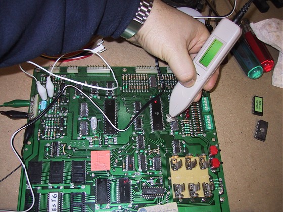
I also use a a
Wittig OsziFox Probescope, which is really a miniature oscilloscope in a
Logic Probe body. While not 100% necessary, its helpful in
determining if the output you're getting is the correct waveform when
diagnosing MPU problems.
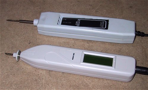
(logic probe at top, scope probe
at bottom)
 Scope
probe in operation (Wittig promo
photo) Scope
probe in operation (Wittig promo
photo)
2.2 In the Machine or at the Bench?:
To do a proper job of testing your
boards, they should be removed from your game and tested at your
workbench. Do this however, you will need an external power supply
to power the boards.
You need a +5vdc regulated
power supply. The best thing to get is a computer power supply,
which also has a +12 volt supply which you can use for the reset
circuit. I took mine out of an old PC we had lying around gathering
dust. If you don't have one, you can get one on EBAY for about $10
including shipping. The older the better, newer PC power
supplies ("ATX" style) do not have off-on switches, you want a
power supply with an off-on switch.
While I don't recommend it, you can use
the test ROM and test the boards while they're still in your game.
REMOVE EVERY CONNECTOR FROM THE DRIVER BOARD AND THE MPU BOARD!!
The only connector that you'll reconnect is the MPU power connecter, IP2
on the right side of the MPU board.
2.3 Get the schematics:
The schematics for the boards will
also be necessary if any of the tests fail. These are in your game
manual and also available in Acrobat PDF form here.
I highly recommend having a printed set of documents for your game that
you leave in the game at all times. You can buy quality
reproduction sets from Pinball Resource.
2.4 Build your test LED (now
optional using the new test ROM):
Several of the tests require the use of
a "test LED" and cannot be performed using a Logic
Probe. Specifically, the memory test and the Special Solenoid test
(see section 5). A logic probe is too sensitive and will show a false good
reading.
Update 10/30/03 - If you are using a
version of the test ROM new than October 2003, then you will no longer
need to use the test LED to perform the memory test. I still
recommend that you make one, it should cost you no more than 50 cents
for a LED and resistor. You'll need it for the special solenoid test
on the driver board and for a MPU test if your LEDs aren't flashing.
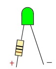
All you need is a LED (any size or
color) and a 1,000 ohm resistor (1/4 or 1/2 watt is fine). Solder the
resistor either leg of the LED and run then solder about 18 inches of
wire to the other leg of the LED and to the resistor. Use
different colors so you can tell positive from negative. I would
suggest attaching some small alligator clips to the end of the leads,
but its not required. If you use stranded wire, be sure to tin the
ends.
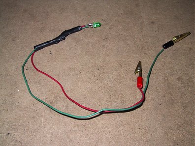 Completed
Test LED Completed
Test LED
2.5 Testing the MPU Baord:
Lets get started. The first step
is to determine where the problem lies. Driver board problems can
also cause the MPU board to lock up, so its important to first test the MPU
board alone to determine where the problem lies.
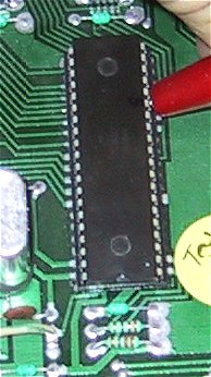
2.5.1 Install the Test ROM. Remove the
ROMs from the board. If they are not labeled, make sure you mark them so
you know where to reinstall them. The test ROM goes into
IC17, which is where Flipper ROM 2 was (the middle socket on a system 6
board.). You
can leave the batteries in the holder.
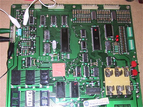
Test ROM in a system 6 board.
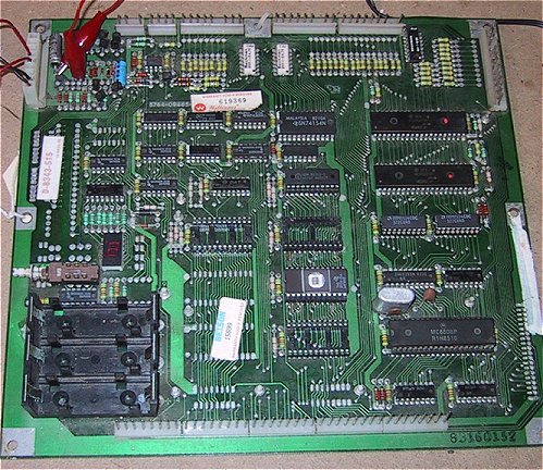
Test ROM in a system 7 board.
2.5.2. Connect the Power. If you are
testing the board on your bench, you'll need to connect it to your power
supply. Connect pin 1 of IJ2 to ground and connect either pin 4,5
or 6 to +5 volts.
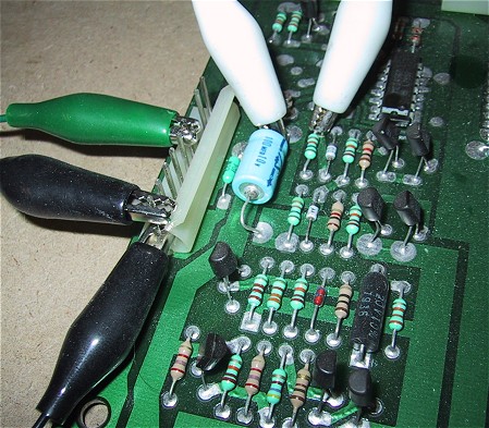
In order to get the test ROM to
work in a system 6 or 7 board, you will need to either supply 12 volts
to pin 9 or the jumper the reset circuit. To jumper a System 6
board, jumper the top leads of R27 and C23. On a
System 7 board, jumper the bottom leads of R27 and
C23.
If you have an "original"
System 3 board without the reset modifications you will also need to
supply +12 volts to pin 9. System 3 boards with the reset
modifications and System 4 boards will boot without any voltage at pin
9.
Power connections and R27 and C23 jumpered on a System 6
board.
Power connections and R27 and C23 jumpered on a System
7 board.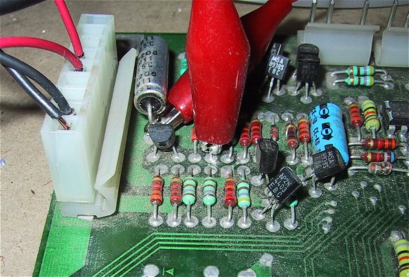
2.5.3 Start the Test. Apply
power and you should see both LEDs blink about once a second. On a System 7
board, the LED digit will blink on and off.
If the LEDs come on and stay on, or
don't come on at all, then your problem is a locked board. Head
down to the troubleshooting section below.
2.5.4 LEDs are blinking, test the
display driver PIA. If the LEDs are blinking, then your board
has booted successfully with the test ROM and you can
continue with the tests. What the test ROM does is to cycle all of
the PIA output ports high and low about every second. Using the
test LED or your logic probe, you can test the outputs of the PIA on the
MPU board (these outputs are used to drive the displays). To use the test LED, connect the negative end to ground
and then touch the positive end to each output on the PIA (pins 2
through 17). I prefer to use a Logic Probe for this since it has a
smaller tip, but the test LED works just fine.
If you don't get a flash on one of the
pins, or one of the pins gives you a continuous signal, then you will
need to replace the PIA.
2.5.5 Perform the Memory Test. To test
the 5101 CMOS and 6810 Static RAM chips (2114 chips on a System 7 Board) you will need to use the
test LED. A logic probe is actually too "sensitive" for this
test and will give you an inconclusive reading.
Using a Test ROM created October
2003 or later:
To run the memory test, press the
diagnostic button on the MPU board (lower button boards with two
buttons).
System 3 to 6 boards:
Test Passed: If all three memory
chips are ok, then the top LED will flash once, then the lower LED will
flash once, then both LEDs will flash. There will be a short
pause, and then the board will continue flashing both LEDs.
Test Failed:
If both LEDs lock on (no flashes) then
IC13 is bad.
If both LEDs flash ONCE then stay on, IC19 is bad
If both LEDS flash TWICE then stay on, IC16 is bad
System 7 boards:
Test Passed: The segment display
should continue flashing
Test Failed:
Segment Display LED shows "1"
- IC13 is bad
Segment Display LED shows "2" - IC16 is bad
Segment Display LED shows "3" - IC19 is bad
If your system 7 board has LEDs, they will also respond like the System
3-6 LEDs.
Using a Test ROM created before
October 2003:
Connect the positive end of the test
LED to +5v and
the negative end to pin 15 on the CPU chip. It should flash on and
off in rhythm with the board's LEDs:
 Although
you can't see it in this photo, what I do is put a small mark using a
sharpie at pin 15 so I can find it easily without having to count down 5
pins each time. Although
you can't see it in this photo, what I do is put a small mark using a
sharpie at pin 15 so I can find it easily without having to count down 5
pins each time.
To run the memory test, press the
diagnostic button on the MPU board (lower button boards with two
buttons). The board's LEDs will stop
flashing (they may stop either off or on, depends on what state they
were in when you pressed the button).
If the test LED stays on without
flashing, then static RAM chip IC13 is bad. If it flashes once,
then stays on, the other static RAMP chip, IC19 is bad. If you get
two flashes, then it stays on, the CMOS RAM chip IC16 is bad.
If all of the RAM chips are good, the
program will return to the rhythmic pulsing of the LEDs.
Helpful hit - I removed IC13 and then
IC16 from their sockets on a good board and ran the test to see what the
results are. This will help you gauge what to expect on a bad
board.
The most common problem is a faulty
5101 CMOS ram chip. Contrary to what you may hear, replacements
are available from a number of sources at reasonable prices. There
are also people who are selling "5101" replacement chips for
upwards of $25 each. These are other CMOS ram chips with sockets
that are wired to mimic the pin-outs on a 5101. You should be able
to find a "real" 5101 in single quantities for no more than $7
each. While these replacements work just fine (and some even
eliminate the need for batteries on the board), you'll do just fine with
a 5101.
Make sure however when replacing a
5101, you use a machined pin socket and don't directly solder the chip
into the circuit board (this holds true for every chip replacement that
you do). A 5101 has 22 pins and its hard to find sockets to
fit. Your best bet is to buy a strip of "SIP" (Single
Inline Pin) sockets, available almost everywhere, and use
them.
Note - there could be several other
causes for memory test failures other than bad RAM chips. If
replacing the 5101 doesn't cure a memory test error, refer the the troubleshooting
section for more information.
2.5.6 Test the MPU board with the
Driver board connected. At this point your board should have
booted (LEDs blinking) and passed the memory test (LEDs flash then start
blinking again). If not, head down to the troubleshooting
section.
Connect the driver board to the MPU
board (power down first!) and then reapply power. The LEDs should
continue to flash as they did before. If they don't, then the
problem is a short on the address or data bus (or both) on the driver
board. Head down to the troubleshooting section.
(note - you may hear the flipper relay
click in rhythm with the LED flashing, this is normal and occurs on
some, but not all boards during this test. More on this in the
Driver Board testing section.)
If the LEDs are flashing, you can
continue on with the driver board tests (go the Driver Board Test
Section) or go to the next step, which is the final MPU board test.
2.5.7 Test the MPU board with the
Game ROMs and the Driver board connected. The final test of
the boards before moving them back into your machine is to put the game
ROMs back into the board. If your boards are working with the test
ROM, but not in your game, chances are you have a bad ROM or ROM socket.
The driver board must remain connected
for this test.
Leave the test ROM in IC17 and first
put IC20 ("Flipper ROM 1") back in. Power the board back
up again and make sure you still get the LED flashing. Repeat this
process for the game ROMs (you may have from 1 to 4 game ROMs depending
on your game). After reinserting each ROM, reapply power and make
sure you still get the flashing LEDs. If the flashing stops with a
specific ROM, then the chip is bad and you'll need to secure a
replacement (more
information is available here).
Finally, remove the test ROM and
replace IC17. When you apply power the LEDs should flash once and
go off. This is the indication that your MPU board has booted with
the game ROMs successfully. Now press the diagnostic button and the LEDs
should flash twice and then go off. If they do go off, your board
has passed all its tests and you can reinstall your boards back into
your game or continue on with the driver board tests.
If the LEDs remain on when you apply
power, head down to the troubleshooting section.

Part Three - Advanced
Troubleshooting Techniques
3.0 Introduction
This part of the document describes
advanced troubleshooting techniques for attempting to determine where
the problem lies. While I have tried to cover most of what can be
expected, these are old boards and it seems like every board I see has a
new or different problem that I've never seen before. I'll
continue to update this section as I run across new situations.
3.1 No LED activity at
all. The LEDs
don't come on at all (system 3 - 6), or the segment display doesn't come
on (system 7). This is usually a
sign of a short on the board or a power problem. Make sure that
you have the power hooked up properly to the board. On System 6
and 7 boards, check the voltage at test point TP9 for +5 volts.
Take it one step further and test for +5 volts at pins 8 and 35 of the
CPU chip (IC1). If
you're not getting +5 volts here, then you need to trace back through
the power circuit to see where you're losing power. Check to make
sure there isn't a short to ground. There are capacitors at the
Vcc connection of each logic chip on the board to ground, check each one
of these for a short. Also check the board very carefully for
solder bridges. If you received the board in this condition, a
prior repair may have gone bad and the board got thrown into the junk
pile. On System 3 to 6 boards,
check for +5 volts at pin 16 of IC2, the 8T28 that drives the LEDs.
Also check for voltage at pins 2 and 5 of IC2. I have seen cases
where both LEDs are bad. Not
having the LED working makes it virtually impossible to continue
troubleshooting your board. The LEDs will always come on unless
turned off by a running program. If you're getting the proper
voltages on the board, but no voltage at pins 2 and 5 if IC2, then I
would suggest following the steps below for checking for a running CPU
chip. If there is CPU activity, then the culprit is most likely
IC2 (8T28) (System 3 - 6 boards). These are discontinued chips and
difficult to find. You can substitute a NTE
6889, they're also hard to find and about $5 a piece.
Mouser occasionally has them in stock. 3.2
No Segment LED activity on System 7 Boards On
System 7 boards, it is common for the 7447 segment driver chip that
drives the LED digit display to go bad. This will give you a false
indication that the board is completely dead or that you have a power
problem. Refer to section
3.3.1 and test for activity at pin 15 of the CPU. If you are
getting flashes, then the problem is most likely the 7447 or the segment
LED itself. You can add two test
LEDs to your System 7 board and continue testing the board before
replacing the 7447 and/or segment LED. All you need are two LEDs
and two 100 ohm 1/4 or 1/8 watt resistors. Solder the two
resistors into the board (see photo below) just to the left of test
point TP9. The LEDs then should be soldered into the two top pads
next to the segment LED (flat side to the left). You can power your board on after inserting the
resistors and hold the LEDs against the pads to determine which
direction they should go if you're unsure of which way to install them. 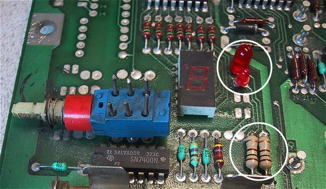
3.3 The LEDs come on and stay
on (test ROM installed). The
most common problem of them all, and the one with most causes. By
default, the 2 LEDs or all of the segments on the LED come on when power
is applied to the board. The need to be turned off by a running
program. The test ROM and the game program accomplish this by
setting the output ports PA6 through PA10 on IC18 low (all
boards). If the test or game program isn't running, these ports
will remain high and the LEDs will stay on. When
the MPU board is first powered up, the CPU chip attempts to read
addresses FFFE and FFFF on chip IC17 (our test ROM or flipper ROM 2) to
obtain the actual address of the program it should be running. This
program then takes over and controls our LEDs. If the program is
not able to start, then our LEDs stay locked on. Game software
attempts to read and write to the RAM chips and to the PIAs during its
initializations steps, so if there is even on problem encountered, the
program will lock up and not turn off the LEDs. The test ROM will
start even if the PIAs or RAM chips are bad, so we can vastly narrow
down the areas to check if the test ROM doesn't start. There
are two major areas to be investigated if the LEDs stay on with the test
ROM installed: 1. Is the
CPU actually running? 2.
Is the test Program running? 3.3.1
Determining if the CPU is running. The
first thing to be checked in troubleshooting a dead board is to
determine if the CPU chip is actually running. I use either a
logic probe or a scope probe and test pins 9 through 20 and 22 through
33 for any activity. These are the address and data bus lines on
the CPU. If the CPU has started, there should be some activity on
these pins. If all are "dead", then the CPU has not
started. If you are getting signals on these pins, then your CPU
is running, but the test program has not started. Go to section
3.4 to determine why. 3.3.2
Check the Reset Circuit (updated 10/30/2003) The
most common reason for the CPU not starting is a bad reset
circuit. If you're testing at your bench, make sure that you have
either jumpered the reset circuit properly (see the top of the document)
or that you have +12 volts at TP1. Using
your DMM, check the voltage reading at pin 40 of IC1 (the CPU)
chip. This should read approx. 4.75 volts. If it doesn't
then you have a problem with the reset circuit. You can override
the reset circuit by applying +5 volts to pin 40 of IC1. If the
reset circuit is your only problem, the CPU will start when you apply
the 5 volts. The reset circuit is
made up of 8 transistors, two zener diodes, one regular diode and a
similar number of resistors. The circuit is a bit different for
each system, so using your schematics, work your way back through the
circuit testing each transistor, diode and resistor until you find the
faulty component. I've found that
in most cases, the culprit is a bad transistor. For System 6 and 7
boards, you can also attempt to isolate the problem by apply +5 volts at
R12 (System 7) or R32 (System 6). If the board boots when you
apply the voltage, then you can restrict your troubleshooting to the
"right" side of the circuit. 3.3.3
Check the voltages at the CPU chip Using
your DMM, make sure you have +5 volts at pins 8 and 35. You should
have a slightly lower voltage at pin 2. Also check for ground at
pins 1 and 21. 3.3.4
Check the CPU Clock Signal System
6 and 7 boards use a 6808 processor which has an internal clock circuit,
while system 3 and 4 boards use the older 6800 processor which requires
an external clock circuit. System
3 and 4 boards: The clock
signal is generated by a Motorola 6875 clock chip. Pray that this
chip isn't bad. When you can find one, they go for about
$18. The clock signal
is input to the CPU at pin 3. If you have a scope probe, you
should be able to see the wave form. If not, use your DMM and you
should see approx. 3 volts at pin 3. You should also be able to
see a waveform at pin 2 of the 6875 (IC5). 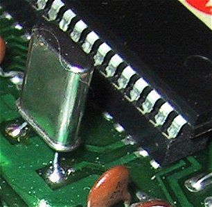
If
you don't get a clock signal or see a waveform on the 6875, I would
suggest first replacing the crystal, they are a lot cheaper (about 75
cents) and tend to fail before the chip. The manual calls for a
3.58 Mhz crystal, you'll find replacements that are 3.579545 Mhz.
Close enough! Replacement crystals are also a good deal smaller than the
originals, so don't panic that you received the wrong part.
Also check
pin 14 for reset voltage and pins 6 and 10 for logic voltage. System
6 and 7 boards: The 6802 and
6808 microprocessors used in these boards contains an onboard clock
circuit. The crystal is connected between pins 38 and 39 on
IC1. You should see a waveform if using your scope probe on these
pins or approx. +3 volts if using your DMM. Absence
of a signal here means either you have a bad crystal or a bad CPU.
Check for continuity across these two pins, I have had boards with
shorted crystals in the past. If you have another (known working)
CPU chip, swap the chip in and check again. If you don't get a
waveform or voltage with the new chip, replace the crystal. For
all boards: If you are using
a scope probe, make sure that the clock signal is
"strong". I have had several boards where the waveform
was oscillating, but just barely. This read fine with a DMM, but
was preventing the board from booting. 3.3.5
Swap the Microprocessor Chip The
microprocessor doesn't go bad that often, I've only run into one in all
of the boards I've worked on. However, if you have a spare lying
around, or another board that works, this would be a good point in the
process to swap the chip. System
3 and 4 boards use a Motorola 6800 microprocessor while System 6 and 7
boards use either a 6802 or 6808 microprocessor. You cannot use a
6802 or 6808 in a System 3 or 4 board! The chips are not backwards
compatible. Either a
6802 or 6808 can be used in a System 6 or 7 board. Most boards all
shipped with 6808 microprocessors (all system 7 boards shipped with 6808
chips). If your board originally had a 6808, you can install
either CPU chip without any jumper changes. If your board has a
6802 chip and you want to use a 6808, check to insure that jumper J1 is
installed and that there is a 6810 RAM chip at location IC13. 6802
CPU chips have internal ram that can used instead of IC13 and the System
6 board is designed to accommodate this. This is why IC13 is
socketed and IC16 is soldered directly into the board. I have
never seen a System 6 board configured to use a 6802, I doubt many, if
any, where ever shipped this way. 3.3.6
Check the IRQ Circuit The
IRQ circuit (Interrupt Circuit) is generated by IC25 (a 4020) on all
boards. Using a logic probe or a scope probe, check at pin 4 of IC1 for
the IRQ signal. You can also check for the IRQ signal at TP5 on
System 6 and 7 boards. If this signal is absent, check the outputs
of the 4020 (pins 12, 13 and 14) as well as pin 10. If you are
getting signals here, but not at pin 4 of IC1, then I would suspect
either IC5 or IC11. 3.3.7
Replace the CPU socket If
everything else looks good, but the CPU still isn't coming alive at all
(no activity on any data or address bus pin) and you have swapped the
CPU chip with a new or known working chip, then its time to replace the
CPU socket. Make sure you use a high quality machined pin socket.
3.4 The
CPU is running but the LEDs are still locked on (test ROM installed) A
much more common problem is a running CPU that is not executing the test
program. The problem usually
lies in a fault on the address or data bus, or in the chip selection
circuit. 3.4.1
Is the program really not running? If
the PIA at IC18 is bad, it may prevent the LEDs from being flashed by
the test program. Using the test LED (not a logic probe!), connect
the negative end to ground and touch the positive end to pin 15 of the
CPU (IC1). If the test LED flashes on and off about once a second,
then the test program is running and you need to replace the PIA at
IC18.
Check
at pin 15 of the CPU for flashes on your test LED .
3.4.2 Is your test ROM good?
Silly
question, but you could waste hours in you have a bad test ROM!
All game chips need to be inserted with the notch end down. If you
by mistake install an eprom upside down, it will fry. When I
create test chips I always test them in a known good game before
shipping them. If you have a known working board, just make sure
your test chip is working before tearing your suspect board apart. 3.4.3
Check for valid signals In
section 3.1 you checked all of the address and data bus pins on the CPU
chip (IC1) and determined that you had most of them running. Now
we need to check to insure that all of the address and data lines are
100% operational. Use your logic
probe for these tests, an alternating flash indicates a valid
signal. You can also use the scope probe and check for a wave
form. Check the CPU (IC1) for
valid address and data bus signals. You must have a valid signal
on pins 9 through 20 and 22 through 33. If the signal is
missing from any one of these pins, there is a problem. Check
IC17 pins 1 through 11, 13 through 17, 19, 22 and 23. These are
the address and data bus lines at the chip. If a signal is missing
from any one of these pins, then you need to trace the line back through
to the CPU to see where it is disappearing. 3.4.4
The 5101 Dilemma When
using the test ROM, you've pulled all of the game ROMs out of the system
which eliminates them as a possible problem. While this rarely
happens, a bad 5101 can cause problems with either the data or address
bus. If your 5101 is already socketed, then I would suggest
removing it until you get your board to boot. If it is the
original chip and is soldered in, if you get stuck and can't find the
problem, then removing this chip will be required. 3.4.5
Address Bus signals The
address bus signals are passed through "buffers". The
signals generated by the CPU chip are not strong enough to work
throughout the MPU and driver board and need to be amplified. This
job is handled by two 8T97 chips, IC13 and IC14. They are easy to
check using either your logic probe or scope probe. Basically, the
CPU is connected to the even numbered pins (2 through 14, with the
exception of pin 8) and the address bus is connected to the odd numbered
pins 3 through 13. CPU line A0 is
on pin 2 of IC4, and the address bus A0 is on pin 3. The signals
should be identical on both pins. The same holds true for A1 (pins
4-5) , A2 (pins 6-7), A3 (pins 10-9), A4 (pins 12-11) and A5 (pins
14-13). You should see the identical signal on both pins.
IC3 is set up the same way, handling address lines A6 to A11. IC8
handles lines A11 through A15, plus the R/W and VMA lines. If
you don't see the identical signal on each pin pair, then replace the
8T97. The part number is obsolete, put can be replaced by a 74LS367,
74LS365 or a NTE 6887. When
checking signals, I always check on the chip pins themselves, not on the
circuit board. If you have a bad socket, this is when you'll find
it. If there is no signal on the chip pin, move down to the board
(the solder pad) and see if the signal is there. Especially if you
have a "Scanbe" socket which are known
failure points. 3.4.6
Data Bus signals The data bus
was originally designed in the same manor as the address bus. Two
data buffer chips or "transceivers" (since signals go
both way on the data bus) were used to amplify the signals. On
System 3, 4 and 6 boards these are the impossible to find 8T28 chips and
on the System 7 board one 74LS245 is used at IC9 (current stock
item). System 6A boards eliminated the data buffers altogether! System
3 through 6: You check
these the same way as the 8T97 address buffers. On System 3
through 6 boards, they are chips IC9 and IC10. Data lines D0
through D3 are connected to IC10 and D4 through D7 are connected to IC9. The
CPU is connected to pins 2/4, 5/7, 9/11 and 12/14. The data bus is
connected to pins 3, 6, 10 and 13. So you should see the same
waveforms on the 2/4 - 3 combination, 5/7 - 6, 9/11 - 10 and 12/14 -
13. If you're not getting the same readings on both sides, then
the chip is bad. If you have a
bad 8T28 in the data bus, you can either replace it with a NTE
6889 (at about $5.50 a pop if you can find one), or under certain
circumstances, you can eliminate the 8T28 altogether. Eliminating
the 8T28 is System 3 through 6 boards: The
story goes that Williams engineers discovered that the two 8T28s could
be eliminated from the data bus if the game ROM was used at IC14 and not
in PROMs at IC22 and IC26. Maybe the older PROMs being used need
more power to be driven, I'm not sure. Since Firepower uses PROMs
at IC21, 22 and 26, I'm really not sure that this is the case. Anyway,
you can safely eliminate both IC9 and IC10 on System 3, 4 and 6 boards
if you switch over to using one of the newer combined game ROMs that
sits at IC14. You
can either use wire jumpers (messy looking!) or my recommendation is to
do what Williams did and use DIP headers. You can order these from
Mouser and then make for a very clean looking job. You
want to jumper:
pin 2 to pin 3
pin 5 to pin 6
pin 9 to pin 10
pin 12 to pin 13 Be
careful when you do this, you can damage your board if the jumpers are
done incorrectly. 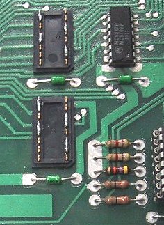
System
4 board with IC9 and IC10 removed and replaced with DIP Headers.
Notice the pins that have been soldered together. 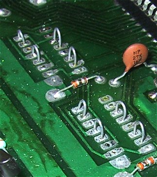
You
can also use jumpers instead of DIP headers to replace the 8T28s. System
6a: System 6a boards do
not use data bus buffers, so there are no intermediate ICs that need to
be checked. Insure that all data bus signals are present on the
CPU chip and the ROM and RAM chips. System
7: System 7 boards use
a single 74LS245 data buffer. The pairs are a bit strange, but
like the address buffers, you want to make sure you get the same
readings on both sides. The pin pairs are 2-18, 3-17, 4-16, 5-15,
6-14, 7-13, 8-12 and 9-11. All
boards: For both the
address and data bus lines check the continuity between lines.
There should be no shorts between any of the data and address bus
lines. Use your DMM and start with address line A0 and check
continuity between address lines A1 through A15 and data lines D0
through D7. Solder
bridges are quite common, especially if chip sockets have been
replaced. If you have just replaced a socket or are testing a
board that never worked, a previous repair attempt may have resulted in
a short. I purchased some boards of off the Mr. Pinball
classifieds and was able to get two of them working by simply fixing
solder bridges from a previous "repair". Best $20 I ever
invested! While you have your DMM
out and are testing address and data lines, its a good idea to test the
lines from IC14, IC17 and IC20 (and IC26 on System 7 boards) back to the
data and address buffer chips. 3.4.7
Chip Selection All the PROMs,
EPROMs and PIAs on your MPU and driver board share the same data and
address bus. Based on the memory location that the CPU is trying
the read from or write to, it needs to "select" the proper
chip. The ROM chips are selected via a chip selection circuit,
while the PIAs are selected directly the address lines. If
the chip selection circuit is bad, the Test ROM will never get accessed
and you board will stay locked. Use your logic probe and check pin
20 of IC17 for activity. If there is none, then the chip is not
being selected. System 3 and 4
boards use a 7442 (IC15), a 7410 (IC11) and a 7425 (IC25) to accomplish
this. System 6 and 7 boards uses a 74LS139 (IC15) along with
IC11 to accomplish this. 3.4.8
The R/W line The
"R/W" line is the Read/Write line. This the signal that
the CPU generates to tell the chip it has selected whether is wants to
read or write data from the chip. This line is high for a read and
low for a write. When the test chip is running (or attempting to
run), this line should be high. It passes through the data buffer
chip IC8 (pins 2 to 3). 3.4.9
The VMA line The "VMA"
line is the "Valid Memory Address" line. The 6800 series
of microprocessors do not always place a valid memory address on the
address bus (in other words, garbage addresses can appear at any
time). The VMA line is high whenever a valid address is placed on
the address bus. The VMA signal is used as part of the chip
selection circuits. If the VMA line never goes high, then a memory
address will never be selected. VMA
originates on the CPU (IC1) chip and is sent to various components on
the board. VMA, like the R/W line, passes through the data buffer
chip IC8 (pins 13 and 14). System
3 and 4 boards have some additional logic chips on the CPU side of the
VMA line, IC7, IC11 and IC12, so it is important to check VMA at the CPU
and pin 14 of IC8. 3.4.10
The "Blanking" Signal This
is the most misunderstood function in the entire Williams
architecture. I think this stems from the test point chart in the
System 6 schematics which show the blanking signal. Testing a
non-booting board will always show 0 volts for blanking, which is then misinterpreted
as a cause, not as a symptom, of a board problem. Mark's law of
Blanking "blanking will always be zero unless the board has
successfully booted with the game ROMs". The
purpose of the blanking signal is to shut down the displays, solenoids
and lamps in case of a software or hardware problem. The blanking
signal works as follows: The
blanking signal is controlled by a timer circuit (a 556 in System 3-6
games and a 555 in System 7 games). If the timer "goes
off", blanking is set low. When the game software is running
properly, port PA2 on PIA IC18 is pulsed every .8 msec. This pulse
is fed into the blanking circuit which resets the timer after the signal
from PA2 goes high and then low again. As long as the timer is
reset before it triggers, blanking will remain high. If the game
program locks up or the CPU stops running, then the timer will expire,
setting blanking low. The key is the signal from the PIA going
from High to Low, the transition is what resets the timer. If the
port sticks high or low, then blanking will be set low (no transitions
are occurring). The symptoms of a
low blanking signal are no displays and no game controlled lights (which
also happens to be the symptoms of almost every other MPU board
problem.) If the board seems to be booting with the game ROMs and
it passes the self test (both LEDs flash and then go off), check the
Blanking signal at test point 4 or pin 37 of the interconnect. It
should be +5 volts. The
most likely cause for a blanking signal failure is a timer chip failure,
a bad capacitor at C31 or a a failure of transistor Q5 (a 2N4403).
In System 3 and 4 boards, the 556 is also used to generate the IRQ
signal, so I would suspect C31 or Q5 first. On System 6 boards the
556 is only used for blanking as is the 555 on System 7 boards. Update
2/10/04 - If you are testing your board using the test chip, the
blanking signal may or may not be present. This is due to the fact
that the test chip pulses port PA2 on IC18 only about twice a second,
which may or may not be fast enough to reset the timer circuit.
DISREGARD THE BLANKING SIGNAL WITH THE TEST CHIP! Blanking can
only be successfully tested once your board is running properly with the
game ROMs. Update
2/20/03 - I've found another chip that can cause a blanking
failure. If your game seems to be booting properly with the Game
ROMs however you're not getting a plus on pin 4 of IC18 (the PIA that
drives the blanking signal), check the outputs of IC25 (a 4020).
If the interrupt signal is not being generated at the correct speed,
then IC18 will not generate the required "pulse". 3.4.11
Miscellaneous Chip Failure OK,
you've gone through all of the above steps and everything looks
fine. What now? If you look at the schematics you'll see a
number of logic chips in addition to the chips already discussed.
These are miscellaneous gates that seem to work with almost every chip
on the board. You may be tempted to start replacing these chips
since you've already done everything else. Be aware that only IC11
(a 74LS10) and IC12 (a 7408) which are in the chip selection circuits,
would prevent the test ROM from booting. Should you replace
these? 3.4.12
Replacing ROM Sockets Much
has been written regarding replacing the sockets on older Williams
boards, especially boards that use "Scanbe" sockets. See
the section below for how to tell if you do have Scanbe sockets on your
board. If you are getting address
and data signals on the solder pads of the ROMs, but not at the chip or
the socket pins, they you definitely have a bad socket that needs to be
replaced. However, just like the board connecters, the socket pins
can corrode and get dirty enough over the years to prevent a good,
steady connection. This is the case with almost all Scanbe
sockets. I have not seen any problems with the much more reliable
RN open frame sockets used on the majority of Williams boards, but if
you can't find a problem elsewhere, then these sockets should be
replaced also. When replacing
sockets, only replace the socket at IC17 until you get the board to boot
properly. The board traces are very fine in this area of the board
and you can cause additional problems by shorting out traces when
replacing the sockets. Be very careful removing the old socket,
and watch for any insulation that may be removed from the traces.
The larger contact area of modern machine pin sockets will short out
traces if any insulation has been removed from the board. 3.4.13
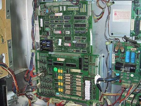
Identifying and Replacing Scanbe Sockets The
photo below shows Scanbe sockets on a System 6 board. These are
extremely low quality sockets that were used on some System 4 and System
6 boards. From what I can tell, Williams either contracted out
production of boards to more than one supplier or ordered sockets from
multiple suppliers, as Scanbe's only seem to show up on about 30% of the
boards. 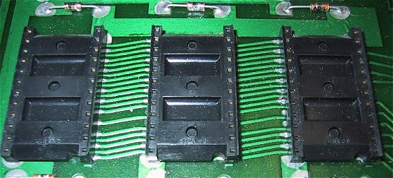
Scanbe
sockets are closed frame, have very small holes for the pin legs and
have the word "Scanbe" molded into the frame near the bottom. 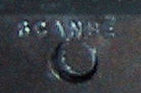
Why are they so bad? The pins are very fine and use pressure to hold the
contacts against only one side of the chip pin. Dirt and corrosion
can cause intermittent connections, resulting in all sorts of problems,
from locked boards to random resets and run away game activity.
Close-up
shot of a Scanbe socket versus a modern machine pin socket. Not to
hard to tell which is better! Always use the best quality
sockets. They may cost 50 cents more each, but are well worth it. 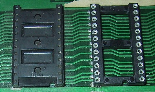
3.5 The
board still fails the Memory Test after replacing the 5101 (added
10/30/03) I've received a
number of emails regarding this issue and I've run into myself quite a
few times. You run the memory test, it shows that IC19 is bad, so
you pull the 5101 and replace it. Then you run the memory test
again, it still shows IC19 as failing! First
you need to make sure that your new 5101 is actually good. 5101's
are very static sensitive and can be ruined by just handling them.
If you have a working board with a socketed 5101, swap the
5101's. I've
purchased 5101's from a variety of sources, and have received a number
of bad ones. Be wary of sellers on the Pinball Newsgroup who sell
5101's in bulk. I've found that at least 25% of the ones I've
purchased from them are bad. Its not that they are intentionally
selling you bad chips, its just that they've bought out old stock of
chips that have who knows where for the past 10 years or so. See
my resources page for a list of dealers that
I buy from and trust. 3.5.1
Check your work There a
several thin traces that run under the 5101. Make sure that you
didn't cut any of these traces when removing the old chip. Use
your logic probe and check all of the chip leads for a signal.
Common sense, but it has saved me hours of work by finding my bad solder
joint. 3.5.2 Chip Select and
R/W line The next area to
check is the Chip Select circuit, which is made up of IC11 and
IC7. Pin 6 of IC11 should be pulse when the memory test is run. The
R/W circuit, which should be working because the board has booted, is
gated through IC27 (System 6) or IC19 (System 7). Check the output
of these chips when the memory test is being run to make sure they pulse
also. |